Many companies have offer restoration parts for those old cars so getting, piston rings, bearings, gaskets, and the like were easy to source. But, not everything has worked out so well.
As with many restoration builds we begin with a conversation about the history of the car, any know problems, and why they want it rebuilt. This vehicle had its own story and reason to rebuild, but it had one ever-present issue. It almost always over-heated when it ran. The customer had the radiator cleaned and recored with no change so we had been tasked with rebuilding and figuring out why the engine was constantly over-heating.
Another special condition was that we received this job already disassembled.
 |
| The impeller was not even attached to the shaft. |
As we sifted through the included parts we definitely found the source of the over-heating. Upon inspection of the water pump we found the water pump impeller not attached to the water pump shaft. It was just dangling inside the water pump housing. It also looked like swiss cheese from someone previously trying to repair the pump with set screws, roll pins, and wood screws (not definite about that one, but wouldn't put it past them)
A short look on the internet and the Hemmings motor news ended without a good supply of a new or used part to replace ours. So we were left with reverse engineering and fabricating one ourselves. This ended up being the best option, because the housing was in such good shape and all that was needed was the impeller and shaft. So here we go. I started by measuring every dimension and taking notes on housing dimensions to see if there was room for improvement. It's a simple straight fin centrifugal impeller that ingests the water in the center (inducer) and exhausts it through its outer circumference (exducer).
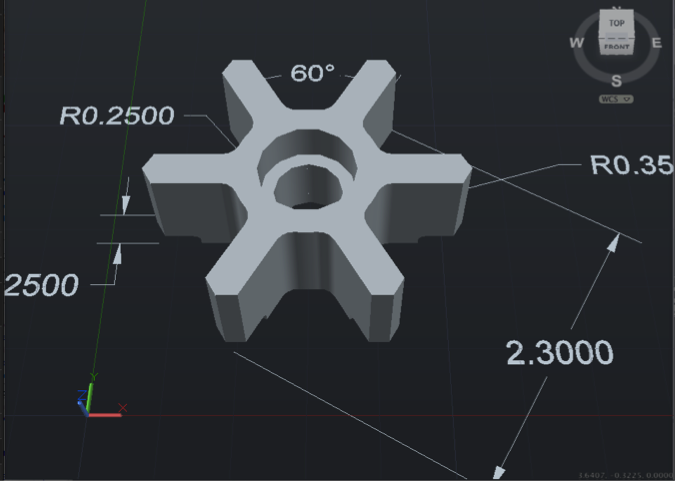 |
| CAD of the component ready for CAM |
I decided to construct it from aluminum for a few reasons: easier to machine than cast iron, easier to get (already had aluminum), and with modern coolants corrosion should be nil. I did increase it thickness by about .050" and its OD by about .050" really to take into account the loss do to erosion.
 |
| Center drilling for the hole which will be the x0y0 of the component. |
 |
| Mounted to the fixture to do the profile of the impeller. |
The stock dimensions are 3"x3"x2". The first procedure was to face the top and two sides so the piece could be held square within the vise. After the facing of the three sides it was flipped over and clamped into the vise. Once over and clamped with the center located the center hole was drilled and reamed which created my zero positions for the x and y axis. Now, being that the part was about 1.200" too thick I needed to cut down the top to the actual thickness of the impeller. With the part now at the final thickness there needs to be a counter bore cut concentric with the center hole.
So all of the machining is done on one side of the impeller and the perimeter needs to be machined for the fins and inducer step. I did this by facing another piece of aluminum and drilling it to accept a 1/2" bolt so the machined part could be held in the center. This allowed full access to the perimeter for milling.
 |
| CNC milling of the impeller. |

And here the final part. The next step will be machining of the pump shaft and reaming of the housing bushing for truing.

Video of the action above
Matt W.
North Texas Speed and Machine
www.ntxmachine.com
I found this post useful.I was trying to find this. Really refreshing take on the information. Thanks a lot
ReplyDeletehttp://www.dinodierensuper.nl/